Class Work
find out more about Caltech or
Stanford
 In AE103, taught by Dr. Hans Hornung, we used Mathematica to map a circle into a Joukowski
airfoil. This can be useful for certain flows which can easily be
solved around a "wing" of circular cross-section. The functions used to map the circle into
a traditional (Joukowski) airfoil can also be applied to the streamlines of these certain flows,
which were easily solved around the circular airfoil. These mapped streamlines then
represent the flow around the Joukowski airfoil.
In AE103, taught by Dr. Hans Hornung, we used Mathematica to map a circle into a Joukowski
airfoil. This can be useful for certain flows which can easily be
solved around a "wing" of circular cross-section. The functions used to map the circle into
a traditional (Joukowski) airfoil can also be applied to the streamlines of these certain flows,
which were easily solved around the circular airfoil. These mapped streamlines then
represent the flow around the Joukowski airfoil.
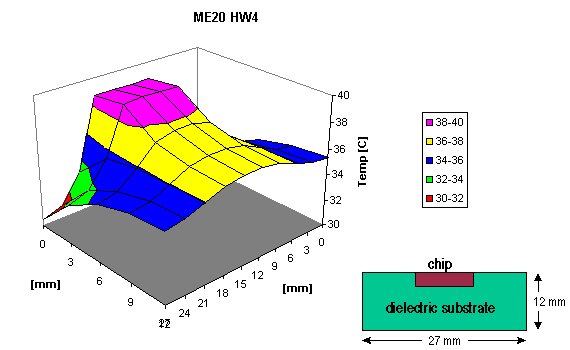
In ME20, taught by Dr. David Goodwin, we solved for a steady-state temperature distribution in
a silicon chip mounted on a dielectric substrate. The solution method employed a
finite-difference technique that was easily programmed into an Excel spreadsheet.
 In ME232, taught by Charles Taylor and David Parker, we used a mapped mesh-generation
technique to create a finite element mesh in a distorted area. Like the Joukowsky method,
the problem is first solved in a simple "parent" domain, and then the mapping used to
transform the parent domain into the actual domain is used to create the final mesh.
In ME232, taught by Charles Taylor and David Parker, we used a mapped mesh-generation
technique to create a finite element mesh in a distorted area. Like the Joukowsky method,
the problem is first solved in a simple "parent" domain, and then the mapping used to
transform the parent domain into the actual domain is used to create the final mesh.
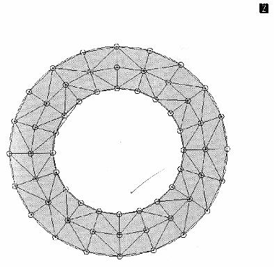
Also in ME232, we wrote a C code from scratch to form a "Delaunay"
finite element mesh in an annular region. A Delaunay mesh is a specific type of mesh which
ensures that the elements have certain desirable properties. Watson's algorithm was used to
create the mesh from a set of node points equally spaced in polar coordinates.
Warning: output makes this task look much easier than it was!
Again in ME232, we experimented with the SPECTRUM software package in order to visualize
complex distributions of flow properties around an airfoil. Warning: output
makes this task look much harder than it was! We were only
responsible for running the visualizer, not solving the finite element fluid problem.
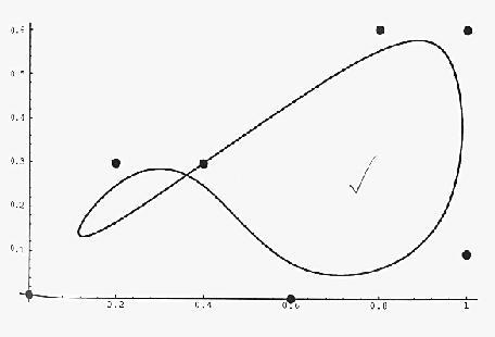
In ME73/171, taught by Dr. Erik Antonsson, we had to generate C code from scratch that
produced a "b-spline" curve-fit between a set of points. This is one of the fundamental
routines that a Computer Aided Design package must use in order to render parts on the
screen.
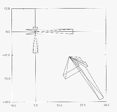
Also in ME73/171, we learned how CAD packages internally calculate projections and viewpoints
which allow the user to quickly and realistically look at a virtual part from whatever
perspective he/she wishes. Any possible rotation, translation,
projection, perspective, or distortion can be calculated with simple matrices.
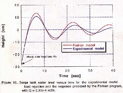
In CE97, taught by Dr. Fred Raichlen, one experiment involved predicting the response of a surge
tank model with Fortran code and verifying results in the laboratory. A surge tank is used to
reduce the detrimental pressure effects of closing a valve, on the plumbing in very large
flows (e.g. water hammer in a sewage line).
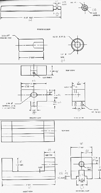
In ME71, taught by Dr. Erik Antonsson, we were given the task of machining a vise out of a block
of aluminum. I know, it's wasteful, but I always recycle my soda cans, so don't call the EPA.
This is not really interesting unless you happen to be one of the engineers that Caltech has
turned out this century who undoubtedly had to machine the same damn vise.
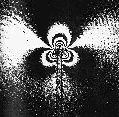
In AE104, taught by Dr. Mory Gharib, we used a relatively new optical technique in order to
visualize (and calculate quantitatively) stress fields around a cracked aluminum specimen.
The technique, called Coherent Gradient Sensing, uses a collimated laser beam to reflect
off of the crack region, pass thru an optical grating, interfere with its sheared component
and project interference fringes on the lens of an ordinary camera.
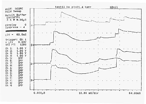
In AE104, we also monitored the pressure at several points inside
inside a 6" diameter shock tube. The shock tube used compressed air, nitrogen,
or helium to rupture a thin stainless steel diaphragm which created the
shock waves we were studying. Despite the linear
flow in the tube, wave reflections made the time-dependent pressure behavior
quite difficult to predict; 3-dimensional supersonic flows around real
aircraft are, of course, much more complex.
In AA256, taught by Dr. George Springer, we
are developing computer codes in MATLAB to perform typical engineering
calculations for composite materials. The anisotropic (directionally
dependent properties) nature of composites makes this task particularly
well suited for the MATLAB set of matrix tools. All properties of the
laminates are represented by matrices and manipulated with linear
algebra. For my benefit, this link is primarily a way to access my
(developing) code from a variety of platforms,
but feel free to use it once it is finished.

[Home |
disclaimer |
acknowledgements |
send Nathan Scandella
email]
Nathan's Classwork page /
nscan@leland.stanford.edu / revised 1/20/97